PISAD ECU Full Simulator
A high-fidelity PowerPC (PPC) emulator for full ECU firmware analysis, defensive automotive security research, and assessment of SecurityAccess (SID 0x27) mechanisms.
Introduction
This project is a dedicated simulation environment for PISAD-based ECUs running on the PowerPC (PPC) architecture — the processor family found in a wide range of automotive engine control units including a wide range of engine control units.
Unlike generic emulators, this tool is purpose-built for automotive firmware analysis. It allows researchers to:
- Load a full ECU binary dump and run it in an isolated virtual environment.
- Interact with the simulated processor at a hardware-abstracted level — including registers, memory, and peripheral I/O.
- Inject custom analogue signals, CAN bus messages, and diagnostic commands (UDS / KWP2000) without touching physical hardware.
PowerPC e200 / MPC5xx UDS (ISO 14229) KWP2000 (ISO 14230) CAN 2.0A / 2.0B Seed/Key (SID 0x27) Flash Memory Emulation
Technical Features & Interface
1. Assembly View & Disassembly Panel
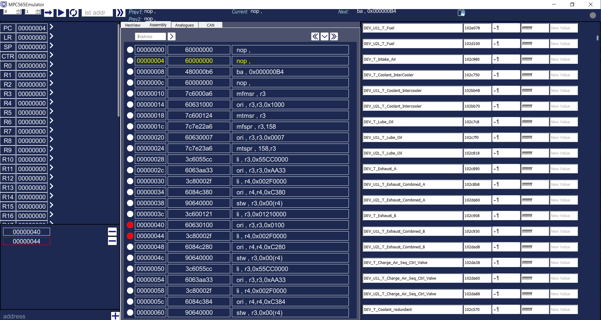
The central execution window provides a scrollable disassembly of the loaded firmware. Each row shows:
| Column | Description |
|---|---|
| Address | 32-bit linear address within the emulated address space |
| Hex Opcode | Raw 4-byte PPC instruction word |
| Mnemonic | Decoded PowerPC assembly (e.g. mfmsr, ori, mtspr, stw) |
| Breakpoints | Red/white dot per row — click to toggle a hardware breakpoint |
The highlighted yellow row always tracks the current Program Counter (PC). Two breakpoints shown at 0x00000040 and 0x00000044 illustrate mid-routine interception of the security seed generation sequence.
0x00000004 and two active breakpoints (red dots) at 0x00000040 / 0x00000044. The right panel lists analogue variable names with their ECU memory addresses and current raw values. 2. Register & Variable Management (Analogue Panel)
Before or during execution, every GPR (R0–R31), SPR (LR, SP, CTR, CR), and software-level variable can be read and overridden via the left-hand register sidebar and the right-hand analogue variable list.
The analogue panel maps ECU software labels (e.g. DEV_U1L_T_Fuel, DEV_T_Intake_Air, DEV_T_Coolant_InterCooler) to their RAM addresses (e.g. 102e078, 102c980) and allows injecting arbitrary values before execution — effectively simulating any sensor reading the firmware would see.
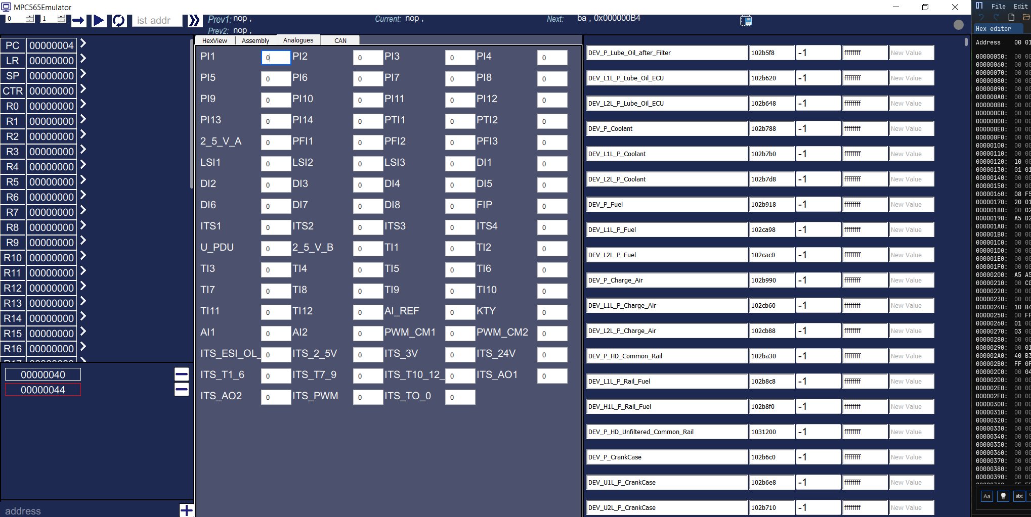
3. CAN Bus Simulation
The CAN tab exposes three independent CAN channels (CAN A, CAN B, CAN C), each with a configurable frame table:
- Index — frame sequence number
- ID — 11-bit or 29-bit arbitration identifier
- Length — DLC (0–8 bytes)
- Data 0–7 — payload bytes, editable per frame
This allows the researcher to replay real-world bus captures or craft custom diagnostic frames (e.g. 0x7DF broadcast requests for SID 0x27) and observe how the ECU firmware reacts without any physical CAN hardware.
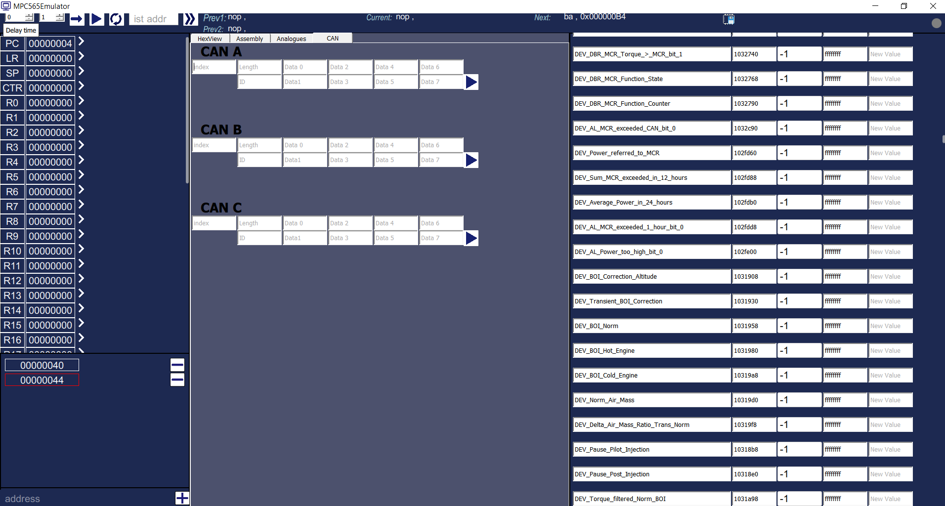
DEV_DBR_MCR_Torque, DEV_BOI_Norm, and DEV_Pause_Pilot_Injection. 4. HexView — Raw Flash Memory Inspector
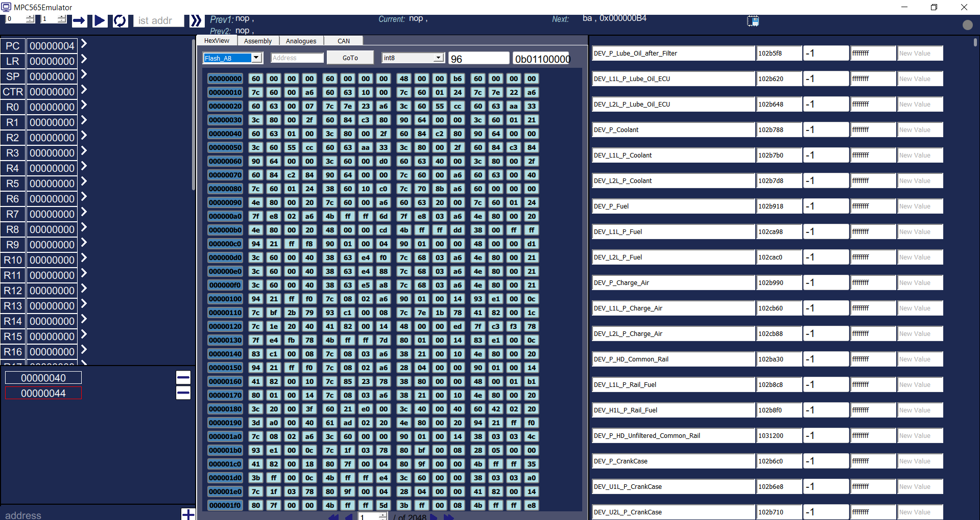
The HexView tab renders the loaded firmware as a classic hex dump, with:
- Region selector (
Flash_AB, internal RAM, etc.) - GoTo address for instant navigation
- Data-type overlay — toggle between
int8,uint16,float32, and more to interpret raw bytes on the fly - Binary representation shown alongside hex for bitfield analysis
Flash_AB displayed from address 0x00000000. The data-type selector (int8 shown) and binary panel (right) allow rapid identification of constants, calibration tables, and constants embedded in the ECU flash. Reverse Engineering Workflow
0x27 — SecurityAccess), you can pause execution at the moment the seed is loaded into a GPR, read it from the register panel, and step through the transformation logic to judge how robust the Seed → Key design is (entropy of the seed, complexity of the transformation, retry limiting) — the kind of review a vendor needs in order to harden it. .bin / .hex / .s19). The emulator maps Flash, RAM, and peripheral register regions according to the MPC5xx memory map.0x27 01 (RequestSeed) frame. The firmware receives it through the emulated CAN controller peripheral and begins executing its security subroutine.Key Capabilities
Full PPC Instruction Emulation
Interprets the complete PowerPC embedded instruction set including mfmsr/mtmsr, mfspr/mtspr, supervisor calls, and all fixed-point, branch, and load/store operations.
UDS / KWP2000 Protocol Stack
Simulates full ISO 14229 (UDS) and ISO 14230 (KWP2000) transport layers over the emulated CAN controller, enabling end-to-end diagnostic session testing without physical hardware.
Multi-Region Memory Map
Separate Flash (AB), internal SRAM, and peripheral address spaces, each independently browsable via HexView with data-type overlays and binary display.
Analogue & Digital I/O Injection
All physical sensor channels (PI, DI, ITS, PTI, PFI, LSI, KTY) and analogue references can be set to arbitrary values before or during execution, simulating any vehicle operating condition.
Hardware Breakpoints
Per-instruction breakpoints set directly in the disassembly view. Execution pauses instantly, freezing all register and memory state for inspection.
ECU Target Support
Designed for PowerPC-based ECU firmware images handled in authorised research and development. Extendable to any PPC-based PISAD variant.
Use Cases
| Use Case | How the Simulator Helps |
|---|---|
| SecurityAccess Strength Assessment | Breakpoint at SID 0x27 handler → step through transformation → evaluate weaknesses and recommend hardening |
| Calibration Table Analysis | HexView + data-type overlay to locate and interpret lookup tables in flash |
| Diagnostic Protocol Fuzzing | Inject malformed UDS frames via CAN panel and observe firmware error handling |
| Firmware Validation | Run production firmware against edge-case sensor values without hardware risk |
| Security Audit | Enumerate all reachable code paths from external diagnostic sessions |
Architecture Overview
┌─────────────────────────────────────────────────────┐
│                  PISAD ECU Simulator                │
├──────────────┬──────────────┬────────────────────────┤
│  PPC Core    │  Memory Bus  │  Peripheral Emulation  │
│  ─────────── │  ─────────── │  ──────────────────    │
│  GPR R0–R31  │  Flash AB    │  CAN A / B / C         │
│  SPR (LR,CTR)│  SRAM        │  Analogue inputs       │
│  MSR / CR    │  Peripheral  │  Digital I/O           │
│  PC tracker  │  Registers   │  KTY / ITS sensors     │
├──────────────┴──────────────┴────────────────────────┤
│              Debugger / Control Layer                │
│  Breakpoints · Single-step · Register override ·     │
│  HexView · Disassembly · Variable monitor            │
├─────────────────────────────────────────────────────┤
│          Diagnostic Protocol Stack (UDS/KWP)         │
│  ISO 14229 · ISO 14230 · CAN frame inject/receive    │
└─────────────────────────────────────────────────────┘